Monday 22 June 2015

What Makes the Rings of Saturn

Introduction

Saturn is a unique planet because of the disc-shaped ring system surrounding it. Galileo first observed the disc in 1610, but thought that it looked more like two large moons because his telescope was not very powerful. In 1655, another astronomer named Huygens was the first to describe the disc as a ring that surrounded, but did not touch, the planet Saturn. He was followed by Cassini, who in 1675 observed that there was a major division in the ring, now called the Cassini Division. This meant that there were at least two rings surrounding Saturn.
Saturn from Hubble Telescope, Nov. 1999
In this Hubble Space Telescope image of Saturn captured in November 1999, the globe of Saturn can easily be seen through the gap of the Cassini Division. (image from NASA and the Hubble Heritage Team)
Today we know that Saturn is surrounded by a huge network of rings, called a ring system, each with unique properties. New information from high powered telescopes (like the Hubble Space Telescope) and spacecraft (like Voyager 1 and 2) have added to our understanding of the rings. The most recent spacecraft sent to Saturn was named Casini-Huygens in honor of the first astronomers to study the ring system of Saturn. This mission consists of the Cassini spacecraft which is orbiting the planet, and the Huygens probe, which landed on Saturn's largest moon, Titan.
Modern images of the rings of Saturn have helped astronomers understand how unique the individual rings are. Saturn has seven major rings, and each major ring is made up of many minor rings. The rings differ from each other in composition (what each ring is made of), rotational speed (how fast the particles of the ring orbit the planet) and appearance (what each ring looks like to an observer).
Saturn's Rings from Voyager 2, Aug. 1981
View from Voyager 2 on 17-Aug-81. This false color image reveals striking compositional differences from place to place within the rings. The blue region in this image is the Cassini Division. (image from the NASA Jet Propulsion Laboratory)
What are the rings of Saturn made of? Why do they look like rings? What makes each ring look unique from other rings? In this experiment, you can investigate how the composition of a ring can change its appearance.

Terms and Concepts

To do this type of experiment you should know what the following terms mean. Have an adult help you search the internet, or take you to your local library to find out more!
  • planets
  • Saturn
  • rings
  • orbit
Questions
  • What are Saturn's rings made of?
  • How can individual particles create the appearance of a ring?
  • How do the properties of each ring make it unique?

Materials and Equipment

  • several sheets of black construction paper
  • glue
  • different types of small particles of different size, shape and color:
    • sand,
    • salt,
    • glitter,
    • rice,
    • beans, etc...
  • an old record player (make sure you ask first!)
  • an old record
  • camera

Experimental Procedure

  1. Select one piece of construction paper for each type of material you will be testing.
  2. Trace the outer edge and the center hole of the record on each sheet of paper.
  3. Cut out the outside of the record shape and poke a hole in the center with a pencil.
  4. Glue the pieces of material to the outer edges of the circle, using a separate circle for each material. The pieces do not need to be tightly packed or uniformly arranged. Think about how pieces of rock and dust might be randomly distributed in the rings of Saturn.
  5. Repeat step four for each type of material and allow all of the circles to dry thoroughly.
  6. After the circles are dry, place your first circle on the record player.
  7. Using a camera, take an overhead picture of the circle while it is still.
  8. Now turn on the record player and take another overhead picture of the circle while it is moving.
  9. Repeat steps 7 and 8 for each type of material.
  10. Print or develop your pictures. Label each picture with the type of material and with "Before" or "After" to keep them organized. You will want to use your pictures for your poster too.
  11. For each material note the appearance before and after rotation, noting the resulting color and appearance of the material.
  12. How do the materials become a ring-like structure? Are some materials different looking than others? How do different types of materials make each ring unique? How do the size and shape of each material change the appearance of the ring?

Friday 12 June 2015

Craters and Meteorites

Introduction

Craters are round, bowl-shaped depressions surrounded by a ring, like the one shown in Figure 1. They are made when a meteorite collides with a planet or a moon. The craters are what make our moon look like Swiss cheese. Each round hole is the place where a meteorite impacted, or hit, the surface of the moon, so craters are often called impact craters. Often, the meteorite that creates a crater explodes on impact, so the crater is an empty reminder of the collision.
Barringer Crater
Figure 1. This is a picture of the Barringer Crater in the desert of Arizona. (David Roddy, USGS)
There are meteors traveling around throughout space, and all of the moons and planets have been impacted by meteorites since the formation of our solar system. (When a meteor hits a planet or moon, it is called a meteorite.) On Earth, we only see a few impact craters because of a couple of different reasons. First, most meteors never reach the Earth's surface because they burn up in the atmosphere. This is what we are seeing when we watch a shooting star during a meteor shower. Second, impact craters from meteorites can be changed by geological forces (like earthquakes and continental movements), or eroded away by atmospheric forces (like wind or rain). There is no atmosphere on the moon, which means that falling meteors do not burn up and there is no weather to erode away the craters. In fact, the footprints of the astronauts who landed on the moon over 30 years ago are still there, perfectly preserved!
Watch DragonflyTV mooncraters video
Where can you find the few impact craters on the Earth? There are only about 170 scientifically-confirmed impact craters on the Earth. Not all of them are obvious because most are eroded, covered by sediment, or under water. Each crater has to be identified using several different kinds of clues. First, geological clues are found by looking for pieces of the exploded iron-rich meteorite, or for glass that formed during the impact. Satellite imaging can be used to visualize crater formations that are beneath the Earth's surface or a body of water. Finally, chemical evidence is used to date the crater and find traces of elements that are more common in space than on our planet.
By piecing together this evidence, scientists can study craters on Earth and link them to different periods of Earth's history. This involves many different types of scientists, including astronomers, geologists, chemists, paleontologists, and meteorologists (who actually study weather, and not meteorites). This has led to an interesting hypothesis being proposed about the formation of a sea, the extinction of the dinosaurs, and even the origins of life!
The craters on both the Moon and Earth come in many sizes. And some are very deep, while others are shallow. Have you ever wondered why? Vanessa and Chris from DragonflyTV did, so they conducted a science project to figure out how meteorite impacts can create so many different-looking craters. They hypothesized that if meteorites hit with different speeds, they would create craters with different depths and sizes. Do you think they were right? Vanessa and Chris really used their marbles for this project—watch the video and find out!
Speed is not the only meteorite variable that could change the look of an impact crater. In this science project you will investigate whether or not the size of a crater depends upon the size of the meteorite. To test this, you will use different sized, nearly spherical objects as your "meteorites," like the objects shown in Figure 2. What types of clues will you look for in your investigation? How will studying an impact crater give you information about the collision, even if the meteorite is no longer there? Are there other clues of a meteorite impact that are important?
Picture of a tennis ball, tomato, and rubber ball.
Figure 2. In this astronomy science project, you will use different sized, nearly spherical objects, like the ones shown here, to act as your "meteorites." How will the size of the meteorite affect what kind of crater it makes?

Terms and Concepts

  • Crater
  • Meteorite
  • Planet
  • Moon
  • Impact crater
  • Meteor
  • Diameter

Questions

  • How do you think the size of a crater is related to the size of the meteorite?
  • What is the difference between a meteor and a meteorite?
  • What is a shooting star?
  • How is an impact crater formed?

Materials and Equipment

  • Different-sized objects that are nearly spherical (at least 3 total), such a rubber ball, a baseball, and a piece of roundish fruit.
    • Tip: Solid objects may work better than hollow ones.
    • Note: Smaller objects, such as marbles and beads, will not work well for this science project unless you use metal or magnetic balls and a magnet to carefully remove them, as was shown in the DragonflyTV video in the Background.
  • Ruler, metric
  • Cardboard box; it should be larger than a shoebox and fairly deep. Something like a small moving box would be perfect.
  • Flour (10-lb bag)
  • Optional: Graph paper
  • Lab notebook

Experimental Procedure

  1. In your lab notebook, make a data table like Table 1.
    1. Be sure to include the types of objects that you will be testing.
  2. Using a ruler, measure the diameter of each of your nearly spherical objects (in centimeters [cm]). The diameter is the distance across the middle of the sphere, from one side to the other. Write your measurements in the data table in your lab notebook. Each object will serve as a "meteorite" in this science project.
ObjectDiameter of Object
(cm)
Diameter of Craters
(cm)
Average Crater Diameter
(cm)
Rubber ball     
Baseball     
Round fruit     
Etc.     
Table 1. In your lab notebook, make a data table like this one to record your measurements and data in.
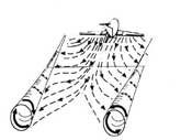
  1. Prepare your meteorite landing area by slowly pouring a 10-lb bag of flour into the cardboard box. Shift the box from side to side to evenly distribute the flour. The flour should be a depth of at least 5 cm in your box. If there is not enough flour, you can either transfer the flour to a smaller box, or add another bag of flour.
    1. When you are done preparing it, you box should look similar to the one in Figure 4.
Picture of a box of flour.
Figure 3. When you are done pouring flour into your box and evenly distributing the flour, your box should look similar to this one.
  1. Now drop one of your "meteorites" into the box by holding the object out at arm's length over the box and letting go. Use the ruler to make sure you drop the meteorite from a height of 50 cm above the flour.
  2. After the "meteorite" impacts the flour, carefully remove the object without disturbing the "crater" left behind.
  3. Repeat steps 4 to 5 two more times using the same object, each time in a different spot in the box. Remember to drop the meteorite the same way and from the same height each time for accurate results. You should now have three craters made by the first object.
  4. Measure the diameter of the first crater by measuring the distance across the center of the depression in the flour, as shown in Figure 4. Be very careful not to disturb the flour with your ruler, by breathing too hard, or by shaking the box. Write the diameter of the first crater in the data table in your lab notebook.
Picture of an impact crater with the diameter labeled.
Figure 4. Measure the diameter of the impact crater by measuring the distance across the center of the depression, as indicated here with a black line.
  1. Repeat step 7 for the other two craters, writing each measurement in the data table.
  2. Calculate the average crater diameter by adding up the three measurements and then dividing your answer by three. Write the answer in your data table.
  3. Prepare your box for the next "meteorite" by shaking it from side to side to even out the flour until it is smooth and level.
  4. Repeat steps 4-10 for all of your objects, each time recording the diameter of the three craters and the averages in the data table in your lab notebook.
    1. Be sure to always drop the meteorites the same way and from the same height so that your results are accurate.
  5. Now make a graph of your data.
    1. You can make a graph by hand using graph paper or use a website like Create a Graph to make a graph on the computer and print it.
    2. On the left axis (y-axis), plot the average diameter of the crater (in cm), and on the bottom axis (x-axis), plot the diameter of the meteorite (in cm).
  6. What size craters did the smallest objects make? What size craters did the biggest objects make? Do you notice any pattern between the size of the crater and the size of the meteorite? What do you think your results tell you about how the diameter of a meteorite is related to the diameter of the crater it makes upon impact

Monday 8 June 2015

Winglets in Wind Tunnels

Introduction

The Boeing jet in the picture at right has winglets at the tips of its wings. Why are they there? What do they do?
As an airplane moves through the air, the wings generate lift by creating an area of low pressure above the upper surface of the wing. The higher air pressure beneath the lower surface of the wing lifts the plane. At the tip of the wing, the high and low pressure air meet.
Diagram of wing tip vortices from a passenger jet.
Figure 1. The diagram shows the expanding wing tip vortices generated by a passenger jet. (NASAexplores.com, date unknown)
The air forms miniature tornadoes, called wing tip vortices that spread out behind the plane (see Figure 1, right). Wing tip vortices cause two problems:
  1. the turbulent airflow they create can be strong enough to flip an airplane that encounters it;
  2. they also increase the drag forces on the airplane that generates them, decreasing fuel efficiency.
Winglets break up wing tip vortices, alleviating both of these problems.
The airflow around winglets is complex. Your wind tunnel should include smoke or fog in the airflow so that you can visualize streamlines along the length of the airfoil. Figure 2, illustrates some design considerations you may wish to consider for the winglets (Hepperle, 2006). A gradual curve transistioning from airfoil to winglet may help to reduce turbulent flow at the corner region. Translating the winglet toward the trailing edge of the airflow can also promote laminar flow at the trailing edge of the wingtip.
Three different winglet designs. From left to right: no winglet, rounded corner, sharp corner, winglet translated toward trailing edge.
Figure 2. Three different winglet designs. From left to right: no winglet, rounded corner, sharp corner, winglet translated toward trailing edge. (Hepperle, 2006)
In this project, you will test airfoils built both with and without winglets in a wind tunnel. Do you see evidence for wing tip vortices when testing airfoils without winglets? Does the addition of winglets alleviate wing tip vortices? Do the winglets increase lift? For winglet-related project ideas that do not require a wind tunnel, see the Variations section.

Terms and Concepts

To do this project, you should do research that enables you to understand the following terms and concepts:
  • airfoil,
  • chord line,
  • mean camber line,
  • camber,
  • aspect ratio,
  • angle of attack,
  • winglets,
  • drag,
  • lift,
  • wing tip vortices.
Questions
  • What are the forces acting on an airfoil in a wind tunnel?
  • How will the addition of winglets affect these forces?
  • How will the addition of winglets affect flight performance?

Bibliography

  • You'll definitely want to check out NASA's Beginner's Guide to Aeronautics. This site is packed with useful information on the science of flight. The "Guided Tours" make it easy to navigate through groups of related pages:
    NASA, 2005a. "Guided Tours of the Beginner's Guide to Aeronautics," NASA, Glenn Research Center [accessed June 8, 2006 ]http://www.grc.nasa.gov/WWW/K-12/airplane/guided.htm.

Materials and Equipment

To do this experiment you will need the following materials and equipment:
  • materials for building model airfoils, e.g.:
    • balsa wood for framework,
    • tissue paper covering,
    • modeling knife,
    • glue,
    • airplane dope.
    • (Alternatively, airfoil sections can be shaped from solid pieces of balsa or other wood.)
  • wind tunnel for testing airfoils

Experimental Procedure

  1. Do your background research so that you are knowledgeable about the terms, concepts, and questions above.
  2. Construct two or more airfoils, identical in shape except for the presence/absence of winglets. See Figure 2 in the Introduction for ideas on different winglet designs you might wish to consider.
  3. Test your airfoils in a wind tunnel. The measurements that you are able to make will depend on the instrumentation available. Desirable measurements are:
    1. lift,
    2. drag,
    3. visualization of streamlines at the wing tip (using smoke or fog).

Tuesday 2 June 2015

Efficient Propeller Design

Introduction

A propeller, like an airplane wing, is an airfoil: a curved surface that can generate lift when air moves over it. When air moves over the surface of a moving propeller on an airplane, the air pressure in front of the propeller is reduced, and the air pressure behind the propeller is increased. The pressure imbalance tends to push the airplane forward. We say that the propeller is generating thrust.
The same principle applies to helicopter propellers, only now the propeller rotates around the vertical axis. The pressure on top of the propeller is reduced, and the pressure underneath is increased, generating lift.
The illustration (Figure 1) defines some terms that are used to describe the shape of a propeller. The radius (r) of the propeller is the distance from the center to the tip. The chord length (c) is the straight-line width of the propeller at a given distance along the radius. Depending on the design of the propeller, the chord length may be constant along the entire radius, or it may vary along the radius of the propeller. Another variable is the twist angle (β) of the propeller, which may also vary along the radius of the propeller.
propeller geometry
Figure 1. Illustration of terms used to describe propellers. The radius, r, of the propeller, is the distance from the center to the tip, along the center line. The chord length, c, is the straight-line width of the propeller at a given distance along the radius. The twist angle, β, is the local angle of the blade at a given distance along the radius (Hepperle, 2006).
In this project you will investigate how changing the chord length affects the efficiency of the propeller. You will keep the other design features (radius and twist angle) constant, changing only the chord length of the propeller. To measure the efficiency of the propeller, you'll connect the propeller to the shaft of a small DC motor. You will use the breeze from a household fan to make the propeller turn, which will cause the shaft of the motor to spin. In this configuration, the motor will act like a generator. You'll monitor the voltage produced by the motor to determine the efficiency of the propeller.

Terms and Concepts

To do this project, you should do research that enables you to understand the following terms and concepts:
  • propeller terms:
    • chord,
    • radius,
    • pitch,
    • rotational speed (measured in revolutions per minute or RPMs);
  • airfoil,
  • forces on an airplane in flight:
    • thrust,
    • drag,
    • lift,
    • weight.
Questions
  • How do you think increasing the chord length will affect the efficiency of the propeller?

Bibliography

  • Wikipedia is a good place to start for basic information on propellers:
    Wikipedia contributors, 2006. "Propeller," Wikipedia, The Free Encyclopedia [accessed November 21, 2006] http://en.wikipedia.org/w/index.php?title=Propeller&oldid=88680042.
  • You'll definitely want to check out the Propellers section (among others) of NASA's Beginner's Guide to Aeronautics. This site is packed with useful information on the science of flight:
    NASA, 2006. "Beginner's Guide to Aeronautics," NASA Glenn Research Center [accessed November 22, 2006] http://www.grc.nasa.gov/WWW/K-12/airplane/guided.htm.

Materials and Equipment

To do this experiment you will need the following materials and equipment:
  • You will need to make or purchase four (or more) different propellers with varying chord lengths, but identical radius and twist angles.
    • One potential source for materials to make these can be found at Freedom Flight Models (scroll down to see the propeller kits).
    • Another potential source for propellers would be a local hobby shop that sells airplane models.
    • If you are handy with tools and experienced with model building, you could also try carving propellers from a soft wood, like pine. It takes quite a bit of skill and patience to keep the twist angle the same for the different propellers!
  • small 1.5-3 V DC motor (e.g., Radio Shack part number 273-223, also available from Jameco Electronics),
  • 1/4 Watt, 4.7 kΩ resistor (e.g., Radio Shack part number 271-1330, also available from Jameco Electronics),
  • jumper leads with alligator clips (e.g., Radio Shack part number 278-1156, also available from Jameco Electronics),
  • digital multimeter (available at a Radio Shack or from Jameco Electronics),
  • fan.

Experimental Procedure

  1. Do your background research so that you are knowledgeable about the terms, concepts, and questions, above.
  2. First you will need to make four (or more) different propellers, keeping the propeller radius and twist angle (pitch) constant, while systematically varying the chord length.
  3. For testing, attach a propeller securely to the shaft of the DC motor. Depending on the materials used for the propeller, it could be taped on to the motor shaft, or drilled and press-fit.
  4. Connect the 4.7 kΩ resistor across the terminals of the motor, and also connect the terminals to the voltage inputs for the multimeter. If you need help using a multimeter, check out the Science Buddies Multimeter Tutorial.
  5. Turn the multimeter to read DC volts, in the range for tens of millivolts.
  6. Starting with the fan on low speed, hold the propeller/motor assembly in front of the fan. You'll want to test in the exact same spot each time.
  7. The propeller may need a small push to start turning in order to overcome the internal friction of the motor. The moving air from the fan should keep the propeller turning after this. If not, turn the fan to the next speed and try again.
  8. Observe and record the reading from the multimeter in a data table in your lab notebook. The reading will fluctuate slightly. You can round the reading to the nearest millivolt. Note that the reading will be quite sensitive to distance from the fan. Make sure that all of your measurements are taken at the same distance from the fan.
  9. The mounting of the propeller to the motor may also affect the reading. If you are taping the propeller in place, you should repeat your measurements after removing and remounting the propeller to see how consistent your results are.
  10. Repeat the measurements for each propeller.
  11. Calculate the average voltage reading from the measurements for each propeller. More advanced students should also calculate the standard deviation.
  12. Make a graph of the voltage produced (y-axis) vs. chord length of the propeller (x-axis). Is there a systematic relationship between chord length and rotational speed of the propeller?