Friday 17 April 2015

A House that Walks

A new prototype house walked around the campus of the Wysing Arts Centre in Cambridgeshire, England.

The eco-friendly house is powered by solar cells and minature windmills, and comes with a kitchen, a composting toilet, a system for collecting rain water, one bed, a wood stove for CO2 neutral heating, a rear opening that forms a stairway entrance, and six legs.

collaborative effort between MIT and the Danish design collective N55, the house walks about five kilometers an hour similar to the walking speed of a human.
The legs reguire a software algorithm to calculate the movement and position of the legs to provide stability over varying terrain.
The house can turn, move forward or backwards, or change height as required and can be programmed with GPS waypoints for traveling to destinations.

image of a waling house

World's Fastest Motor

A new motor developed by researchers at ETH Zurich's Department of Power Electronics and marketed by the Swiss company, Celeroton, can spin in excess of 1 million revolutions per minute.

image of a high speed drillAs a comparison, collapsed stars spin at 60,000 rpms, a blender at about 30,000 and high performance engines at around 10,000 rpms.

The matchbook-sized motor has a titatnium shell, ultra-thin wiring and a trade secret iron formulated cylinder. The need for smaller electronic devices requires smaller holes, which means smaller, faster, more efficient drills.

Thursday 16 April 2015

Vein Identification

image of hand scan

Another technology innovation is the biometric identification and security device known as PalmSecure.

It works by identifying the vein pattern in the palms of our hands. Similar to our fingerprints, vein patterns are unique to each individual. 

The purported advantages of this technology is that it is less expensive, 
easier to manage, and is more reliable 
than traditional methods of identification.

Air Into Water

Johathan Ritchey has invented the Watermill, which is an atmospheric water 
generator. It converts air into fresh water.
image of a fresh water generator
This latest technology invention produces fresh water at a cost of about 3 cents a liter (1 quart). Originally designed for areas that do not have clean drinking water, the Watermill is for households that prefer an eco-friendly, cost effective alternative to bottled water. 

Atmospheric water generators convert air into water when the temperature of the air becomes saturated with enough water vapor that it begins to condense (dew point).

"What is unique about the Watermill is that it has intelligence," says Ritche. This makes the appliance more efficient. It samples the air every 3 minutes to determine the most efficient time to convert the air into water.

It will also tell you when to change the carbon filter and will shut itself off if it cannot make pure clean water.

Car Gps Tracking

image of gpsCar Gps Tracking is fairly common in new vehicles, providing drivers 
with tracking and navigation. 

However, latest technology inventions have made car gps tracking systems more sophisticated, allowing for a wide range of additional uses.

Smartbox technology is one example of how car gps tracking systems are being used to lower car insurance.

A comprehensive recording of a driver's habits allows insurance companies to provide "pay-as-you-drive" car insurance.

City officials in New York City are considering how car gps tracking could be used as "Drive Smart" technology.

Most large cities have a limited capability to change the infrastructure 
of their roadways.

A car gps tracking system that integrates with traffic information would give drivers the ability to select routes in real time that were more fuel efficient, less congested, faster or shorter.
A driver's recorded routing selection could then be used to penalize or reward drivers by lowering or increasing their related licensing fees or by calculating mileage based "road-use" fees.
Eventually, such a system would replace gasoline tax since these revenues will decline as more vehicles become less dependent on fossil fuels.

3D Printed Car

image of Strati 3d printer carThe latest technology inventions in 3d printing are rapidly changing how things are being made.
It's an emerging technology that is an alternative to the traditional tooling and machining processes used in manufacturing.
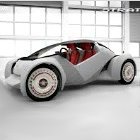
At the International Manufacturing Technology Show in Chicago, a little known Arizona-based car maker created a media sensation by manufacturing a car at the show.
It was a full scale, fully functional car that was 3d printed in 44 hours and assembled in 2 days.


The car is called a "Strati", Italian for layers, so named by it's automotive designer Michele Anoè because the entire structure of the car is made from layers of acrylonitrile butadiene styrene (A.B.S.) with reinforced carbon fiber into a single unit.
The average car has more than 20,000 parts but this latest technology reduces the number of parts to 40 including all the mechanical components.
“The goal here is to get the number of parts down, and to drop the tooling costs to almost zero.” said John B. Rogers Jr., chief executive of Local Motors, a Princeton and Harvard-educated U.S. Marine.
“Cars are ridiculously complex,“ he added, referring to the thousands of bits and pieces that are sourced, assembled and connected to make a vehicle.
"It's potentially a huge deal," said Jay Baron, president of the Center for Automotive Research, noting that the material science and technology used by Local Motors is derived from their partnership with the U.S. Department of Energy’s Manufacturing Demonstration Facility at the Oak Ridge National Laboratory in Oak Ridge,Tennessee.
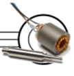
This technology can use a variety of metal, plastic or composite materials to manufacture anything in intricate detail.
People tend to want what they want, when they want it, where they want it, and how they want it, which makes this technology disruptive in the same way digital technologies used by companies like Amazon and Apple disrupted newspaper, book and music publishers.
Imagine if you could customize and personalize your new car online and pick it up or have it delivered to you the next day at a fraction of the cost of buying one from a dealership?
What if you could make a fender for a Porsche, or a tail light for a Honda, for a fraction of the cost of buying from a parts supplier? How revolutionary would that be for the automotive industry?

It's already happening.

Jay Leno, the former Tonight Show Host and avid car enthusiast is famous for his collection of vintage automobiles.


One of the challenges with collecting antique cars is replacing parts. You can't buy them because they're obsolete and having a machinist tool the part doesn't always work and often requires costly modifications until the part fits.
So Leno uses 3d printing technology to make parts for his cars. "These incredible devices allow you to make the form you need to create almost any part", says Leno.
John B. Rogers Jr. believes that in the near future a car will be made in just 60 minutes.
The company is already organizing a worldwide network of "Microfactories" where you can order and pickup your personalized, customized car.

Servo Controlled Marble Maze Build 2

Picture of Servo Controlled Marble Maze Build 2
This is an updated build based on a previous Instructable. This one is easier to make and looks a little better. In addition, some new building techniques like using magnets to attach the Lego maze are kind of cool.
The project is for a web site that lets you control this device over the Internet. As before, since it's a web site with latency (no Wiimotes), there are only 4 commands: Up, Down, Left and Right. So the maze itself has to be designed carefully to work with only those primitive commands, and those designs are covered here.
This Instructable is about the mechanical build of this project. Other ones cover the web control. For local control with an Arduino, this Instructable has the controller design and code to make it run. I have also attached the latest version of the local control code to the last step of this Instructable.

Step 1: Parts

Metal, Wood & Misc.
6.5" of angle aluminum 1.5" x 1.5" x 1/16" thick
4 feet of aluminum bar 1.5" x 1/8" thick - 1/16" might be OK too. I had some nice anodized bar, but any kind will do.
Plastic sheet - 10" x 10" x 1/16" thick. I recommend polycarbonate/lexan since it's less likely to crack
1x Lego bricks
Marble - the right size marble for two Lego studs is 9/16" (14mm), which is common on board games. Land of Marbles has many colors and styles available in this size.
1x4 pine - about 5 feet
Servos - Hitec HS-5645MGs are recommended

Hardware
I use McMaster-Carr to order the stainless screws, nuts and washers, but you can get most of them at a local hardware store. The wood screws were from the local home store.
(4) 3/8" long #8-32 pan head socket screws for the X Axis brackets to plastic mount
(4) #8 flat washers, split lock washers, and hex nuts - Keps nuts can be used for these instead
(8) 1/2" long #8-32 pan head screws for the Y Axis bracket
(8) #8-32 Keps nuts
(4) 3/8" long #6-32 pan head screws for mounting the servos (two per servo)
(4) #6-32 split lock washers + hex nuts
(2) 1/4" long #4-40 pan head screws for the X Axis servo horn
(2) 3/8" long #4-40 pan head screws for the Y Axis servo horn (the aluminum is thicker)
(2) 3/4" long #4-40 pan head screws for the pivots
(6) #4-40 nuts - maybe a couple split lock washers and flat washers for the pivots would be good.
(8) 1 58" long drywall screws
(4) 3/4" long #8 mod truss lath screws

Step 2: Building the Platform and X Axis

For the platform, I used a square piece of polycarbonate plastic. Polycarbonate is nicer than acrylic since it will not crack when being drilled and cut. Since the Lego base is 10" square, I made the plastic that size also.
We need to attach a servo horn and a pivot to the base, so I cut a couple of 1.25" pieces from the 1.5" x 1.5" x 1/16" aluminum angle. I actually cut three of them since we need one more in the next step.
I drilled four 3/16" holes in each piece for mounting on the platform, but in the end, I only used two of them for mounting - I used a pair of diagonal holes. I marked the holes in the plastic using the brackets as templates - I held the plastic vertically on a table to make it square, and held the bracket against it to mark the holes. The heads of the screws stick up where the Lego plate will be, but the magnet attaching system I used is taller, so that is not an issue.
On one bracket, you only need a 7/64" hole in the center for the 3/4" long #4-40 screw.
On the other bracket, you need a large hole in the center for the servo horn. Ihighly recommend a step drill for this - it is much safer and easier for these larger holes. On the servo horn, I drilled out two of the holes with the 7/64" bit, and traced them to the bracket and drilled the bracket. 1/4" long #4-40 screws were used to hold the servo horn to the bracket.
To attach the Lego plate to the plastic base, I used pairs of magnets - one pair in each corner glued to each side so the Lego plate can be removed easily for work. I used super-glue (cyanoacrylate) and you need to be careful not to glue the magnets together! So, I put drops of glue on the plastic and stuck the magnets to the glue rather than putting the glue on the magnets. Once those dried, I put glue on the Lego base and pushed it on top of the magnet pairs.

Step 3: Building the Y Axis

There are a couple ways to make the Y axis. I used 1/8" thick aluminum bar and bent it. 1/16" might be fine, and would be a lot easier to bend. You could also make corner brackets from angle aluminum or use standard brackets and just 4 straight pieces of aluminum. That may make the construction easier since bending the metal perfectly can be tricky, though bending is very quick to do, and the bracket approach may be heavier and requires a lot more screws and holes.
For this project, the Y Axis was 11.25" x 12". For the bending approach, I split one of the 12" sides up for the bracket. In my case, with the 1/8" metal joining plate opposite the servo allowed them to balance out nicely so the servo does not need to struggle to hold it level.
To join the loop, I used a 1.5" piece of bar, and drilled 3/6" holes and used #8-32 1/2" long screws with Keps nuts. I drilled the 8 holes in the joining piece first, then traced those holes on the Y axis, laying it flat on a table to make it line up nicely. With the corner bracket approach, this step would not be necessary.
On one side of the Y Axis, the servo for the Z Axis needs to be mounted. I traced the servo outline, making sure the servo horn was in the middle of the side. The servo body will be a little off-set. Then I used a Dremel tool to cut out the rectangle, and filed it square and smooth. To mount the servo, I used the servo itself as a guide, and drilled two 7/64" holes for the #6-32 screws to mount it. I used a screw, a split lock washer, and a nut to hold them - there was not enough room for a flat washer.
On the opposite side from the servo, at the joining bracket, drill a 7/64" hole for the pivot to fit in to.
A servo horn and pivot need to be added to the Y axis - just as in the previous step.

Step 4: Building the Base

There will be one servo bracket and one pivot on the base. One side of those angle aluminum pieces can be trimmed to 3/4" wide since they will rest on the pine boards. The pivot is just one more 1.25" long piece of angle aluminum, with a 3/16" hole in it.
You can buy servo brackets or make one - see the picture for one way. For the one I made, I used a 2.5" long piece of the 1.5" x 1.5" angle aluminum.
The base can be made of of wood. I used high quality 1x4 boards. Two of them were 15" long, and two were 13.25" long - those were critical to make sure the servo and pivot fit perfectly. I used 1-5/8" drywall screws to hold them together. I pre-drilled the holes with a counter-sink drill since they were close to the edge of the wood.
The pivot is centered on one of the 11.25" sides, and the servo bracket on the other side - make sure to center the servo horn, not the servo body, which will be a little offset.
I drilled a couple 3/6" holes in the bottom of the two brackets and used 3/4" long #8 lath screws (large pan heads) to screw them into the wood.

Step 5: Maze Design

With only four primitive moves (Up, Down, Left, Right), designing the maze can be a challenge. You can't turn the marble in the middle of a hallway, so some special designs are needed. See the picture for the shapes that allow branching. The center of the patterns can be different sizes, and possibly not be used at all, but having something there helps keep the ball on track if it is not moving exactly straight. Those designs have four exits, but you can block one of them to have three.

Step 6: Servos

I have tried a few servos with this project. Standard ones will work, but will be a bit unsteady holding the level position. I also have used Hitec HS-645MG servos since they did much better holding the level position. For this project, though, I switched to Hitec HS-5645MG digital servos since they have plenty of holding power without jittering on the level table, and the dead band can be adjusted for the table leveling if necessary.
The latest Arduino code for the local control mode is attached. Have fun! This is a great project for kids of all ages to play with.

Wednesday 15 April 2015

Combining MakeyMakey, CircuitScribe and Scratch to Create Art

Many valuable Instructables have been written about MakeyMakeyCircuitScribe, and Scratch. Once you have mastered the basics of each, you can begin to combine them into even more useful projects! This project combines all three. My daughter and I created this project to demonstrate one possible combination. We just hope that it's a useful combination.
Never heard of them? Here's an introduction to the introduction. :-) CircuitScribe is a suite of products that enable beginners to test out electric circuit ideas. It includes a pen that draws conductive ink. Electricity flows along the ink, and through the circuit elements supplied in the products. (This project does not use any of the circuit elements.) MakeyMakey is a product that translates "on" and "off" signals into codes that a computer "sees" as computer keyboard keystrokes. Finally, Scratch is a programming environment designed to help people - especially younger kids - have fun while learning the basic of computer programming.
If you haven't heard of them, you might want to check out Instructables specific to them - there are plenty here!
Why combine them? Each of those tools achieves a few specific goals. CircuitScribe carries electricity around on a hard surface, like paper. MakeyMakey turns an electric signal into a sequences of ones and zeroes that a computer interprets as keyboard keypresses, and Scratch can turn keypresses into motion on its "stage."
The real goal of this project was to demonstrate the ability to combine these tools. With them, you are limited more by your imagination then anything else!
However, the project could allow a choreographer to control a simulated dancer's movements, just by tapping on a piece of paper. Tap in one spot, and the dancer jumps into the air and lands again. Tap in a different spot, and the dancer performs a pirouette.
This Instructable includes pictures of the circuits and a description of them, but we assume that you have previous experience with MakeyMakey and Scratch. Later, we use a video to show just the key part of the Scratch project that accepts keyboard (and MakeyMakey!) input which controls a dancer. A link to the Scratch project is provided later so that you can see the way that it all works together.

Step 1: CircuitScribe Tap Pads
Moving the dancer starts with the user tapping a spot or line on a piece of paper. In the following picture, you can see three silver lines, with an alligator clip attached to one end of each line. Each line was drawn with a CircuitScribe pen. We found that the ink does not flow fast enough that we could consistently draw a long continuous line - small blank spots are left on the paper, and the electricity can't jump across those blanks. So plan to go over the lines two or more times. You can save some ink by looking for little gaps and filling them in, but that isn't always enough.
The middle line is labeled "Restart" - it's easier to see in the second picture, which is just a zoomed-in version of the first picture. Tapping that line ("tap pad") will return the on-screen dancer to her original position. The other lines will be named "Split" - to make the dancer do a split - and "Tilt Jump", etc.
To complete this step, draw lines and label them with the dance moves you want the dancer to do.

Step 2: MakeyMakey: Converting Electrons into Letters and Numbers

As we mentioned earlier, the purpose of MakeyMakey is converting small electric signals into the ones and zeroes that the computer interprets as numbers and letters. This step connects those "tap pads" to the MakeyMakey circuit board, which then sends the correct pattern of zeroes and ones to the computer's USB port.
Assuming you've used MakeyMakey before, this step is straightforward. For our purposes, it converts each "tap pad" into a letter, number, or space. Each of those will be interpreted by the Scratch program into a movement of the dancer.
Even if you're new to MakeyMakey, this step is not difficult. Each jumper cable (those wires with alligator clips at the ends) should "eat" the edge of the paper with the ink lines at one end. The clip's "mouth" must make contact with the ink, for electricity to flow. The other end of the cable gets attached to the appropriate point on the MakeyMakey circuit board. (See the pictures at the top of this script.)
You will need to do a little bit of "data management." It may be helpful to write a chart that "maps" the label on each ink line - the dance moves - to a particular letter or number. For example, you might choose the letter 'S' for Split.

Step 3: Scratch: Dancing on 1's and 0's

If you have used these tools even a little bit, the last step will take the most time, but it's the most fun! You finally get to see the dancer move, and you get to decide what she (or he) will look like.
If you have written Scratch projects before, you may only need to watch the video below, and then review the project.
Each Scratch project starts with choosing a background and the "costumes" for the sprites. A "costume" isn't clothing, it's what the sprite looks like. For this project, the costumes are the dancer in different positions. Fortunately, the Scratch library provides a basic set of dancers in a few positions. We copied some of them and modified them to make all of the positions that we needed. You can choose any set of costumes you want, or draw your own, or, if you're a dancer, you can have a friend take pictures of you in different poses and import them into Scratch.
We chose a backdrop and costumes, and created clickable sprites (buttons). The user can click on the buttons, or type letters on the keyboard, or use the tap pads described above. (See first picture at the top of this step.)
After you have at least a few of the costumes that you want to use, you can begin writing scripts for the Ballerina sprite and the button sprites. Here is an example of a script for button sprite named "Split". It simply responds to those two actions - although one of those actions ("press W") can be achieved by using the keyboard, or a tap pad that you made earlier in this Instructable. (See the two brief scripts at the top of this step.)
Those two scripts broadcast the message "Split". A script for the Ballerina sprite simply changes the costume from the current costume to the "ballerina-c" costume. (Click on the last picture for this step.)

Step 4: Putting it all together

Now that you have seen the pieces, let's take a narrated look at some of the Scratch details, and the whole project in action. We hope you enjoyed this project, even if you only learned a few ideas from it!

Step 5: Acknowledgements
We would like to thank Kathy Ceceri for teaching us about MakeyMakey and CircuitScribe at an Instructables Build Night at the Tech Valley Center of Gravity!

RC Aircraft Thrust Stand Version 2 - Hack of a Kitchen Scale for only $10

Using a standard kitchen scale purchased from amazon (Item # B00MN0NI90 or search for "DecoBros Digital Food Scale") for $10 and some 3D printed parts, you can make an RC Aircraft Thrust Stand to measure thrust produced across the operating range of an RC motor and prop combination. Using a standard RC watt meter you can now also measure efficiency and better match props, batteries, and motors. Building a custom Quad, a 3D aircraft, or gentle flyer that you want ultimate flight time on, this is a must have.

Step 1: Pop the back off the Scale

A couple screws and some tabs and you have gained entry into the scale. The arrows show the scales feet attached to the sensor plates (metal plates with strain gages). Each one of these provides input in to the central processor that sum the strain (bending of the metal plates) and displays that force as pounds or grams. Bend back the tabs and remove the sensors from the scales frame. Careful of the wires and do not bend the metal plates.

Step 2: Cut the plastic frame of the scale

Leaving the electronics in tack, cut the plastic frame of the scale as shown. I used a cut off wheel on a dremel type tool. Clean up the edge to the webbing frame as shown. Using a pair of flush cut pliers, (not the dremel), nip the plastic nibs that hold the plastic feet on the sensor plates. You do not want to damage or bend the sensor plates, these are calibrate to measure force and any change to the way they bend will cause false readings.
Side note: I clip off the coin cell holder and used a 2 AAA battery hold from RS in it's place. (Don't solder until later, if you decide to do this; but you don't have to.)
You're scale is ready to be reused as a thrust measuring device.